


Design of intakes and outfalls to avoid risks during operation

DOWNLOAD THE PAPER
Abstract
The authors, engineers of the Consulting Company Increa, have significant and valuable experience in the design of marine installations (intake and outfall pipelines and intake structures) for desalination plants (Pita, 2014 and Pita, 2019). Increa’s engineers have been designing marine pipelines and structures for multiple plants throughout the world and in various different operating environments.
This paper describes some of the problems that can be experienced during the operation of desalination plants and the way these can be prevented during the design stage. Proper design of marine installations should consider the most probable situations that can occur. In addition to normal operation, designers should consider accidental situations and the risks associated with these should also be evaluated and mitigated.
Introduction
The main author of this paper has been working in the design of marine outfalls and intakes for more than 25 years. They have also given technical support for repair or improvements for desalination plants where there are operational and/or structural problems.
External hydraulic "over-pressure" at intakes pipes and structures
The structural design of the pipe needs to consider the longitudinal resistance of the pipe when sinking it and its transversal resistance against excessive ovalisation and buckling.
In this paper, we focus on the transversal resistance against buckling. One of the actions to consider in this analysis of an intake pipe is the difference between the external and internal hydraulic pressures (AWWA M55, AWWA M45).
The formulae for considering the allowable buckling pressure (PcA and PUA) are defined in chapter 5 of the Manual of Water Supply Practices M55 (PE Pipe, Design and Installation), provided by the American Water Works Association and are explained later in this paper. In the case of buried pipes, the allowable pressure depends mainly on the stiffness of the soil around the pipe and the circumferential stiffness of the pipe. In the case of unburied pipes, that pressure only depends on the circumferential stiffness of the pipe (as there is no soil around). This allowable buckling pressure should be larger than the acting pressure.
The acting pressure includes the weight of the fill (and other charges on the ground surface) over the pipe and vacuum pressure (in our case, this is due to the difference between external and internal pressure). The further from the intake point, the larger the vacuum is. If the project only considers the theoretical piezometric line at long term, it can omit some situations that can happen, for instance, when there is a blockage of the intake structure, or when the head losses are larger than estimated and the pump system deals with them by pumping water from a lower level in the pump sump.
Figure 1 shows what can happen in operation: the hydraulic designer fixes a diameter for the intake pipe, so that submergence of the pump is enough at the worst situation expected: dirty pipe and lowest sea level. This is represented in pink color and the difference of hydraulic pressure between external and internal is marked with a vertical black arrow. If there is a problem with the roughness of the internal surface of the pipe, the headloss increases and the pumps could continue working, with problems of vibration or vortices. As there is a need of water at the plant, the system would continue working (poorly) with the piezometric line shown in green. This situation leads to a higher “external overpressure” and the pipe safety against buckling is reduced.
The red line shows what can happen if an increase of head loss happens at the intake structure. The increase of “external overpressure” not only happens at the pipe, but also at the intake. If there is a blockage of the water entrance into the intake structure, for instance, due to the presence of suspended solids of large size, jelly fish, etc. and the operator continues pumping water, then a large drop of pressure occurs between the sea and the interior of the intake tower. This not only affects the pipe, but also the intake structure, where structural problems (breakage of the most sensitive elements) can happen. It is essential to have an operation manual and controls, so that the plant cannot keep pumping water when the pumped flow is less than expected for the corresponding water level in the pump chamber.
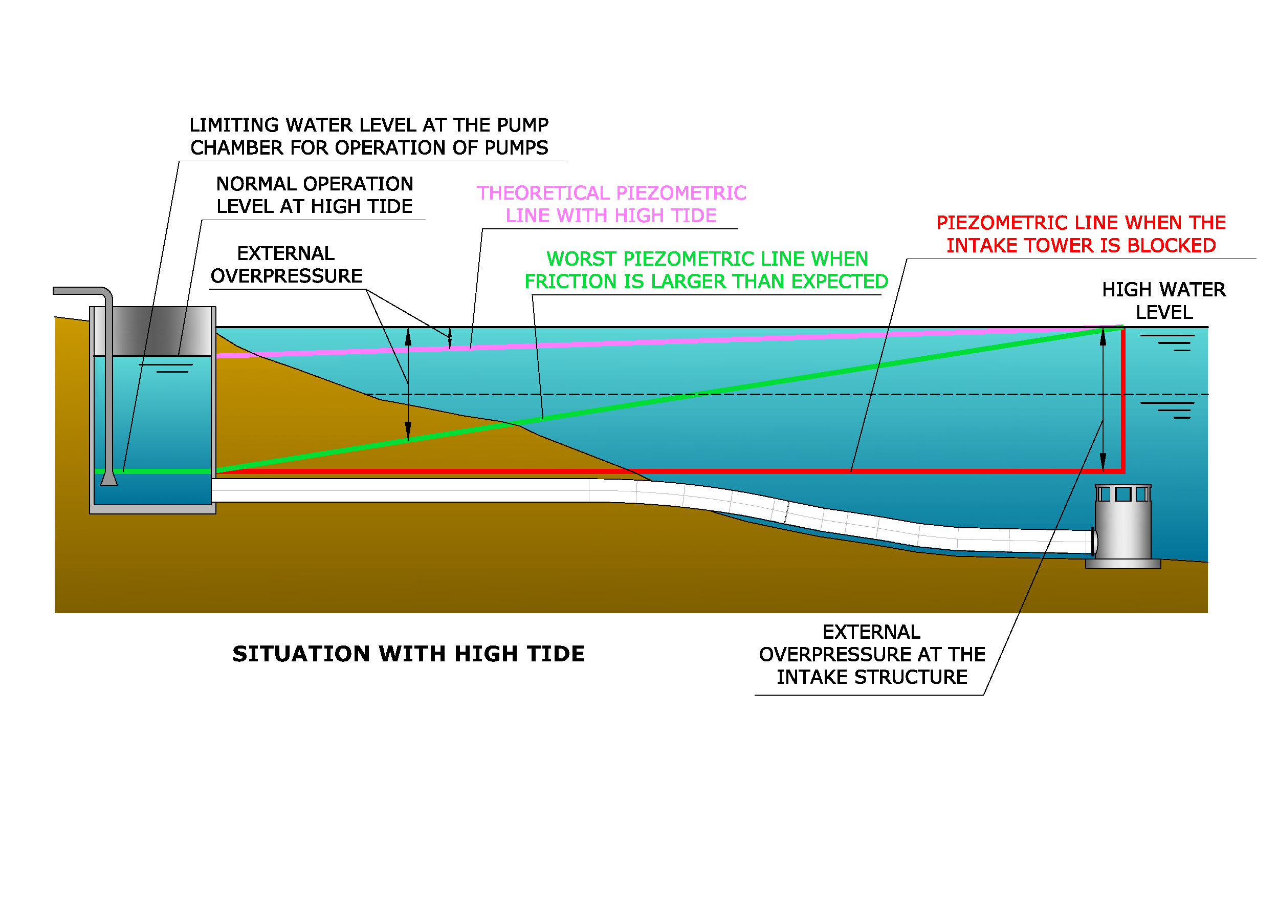 Figure 1: Different piezometric lines during operation of an intake (low sea level)
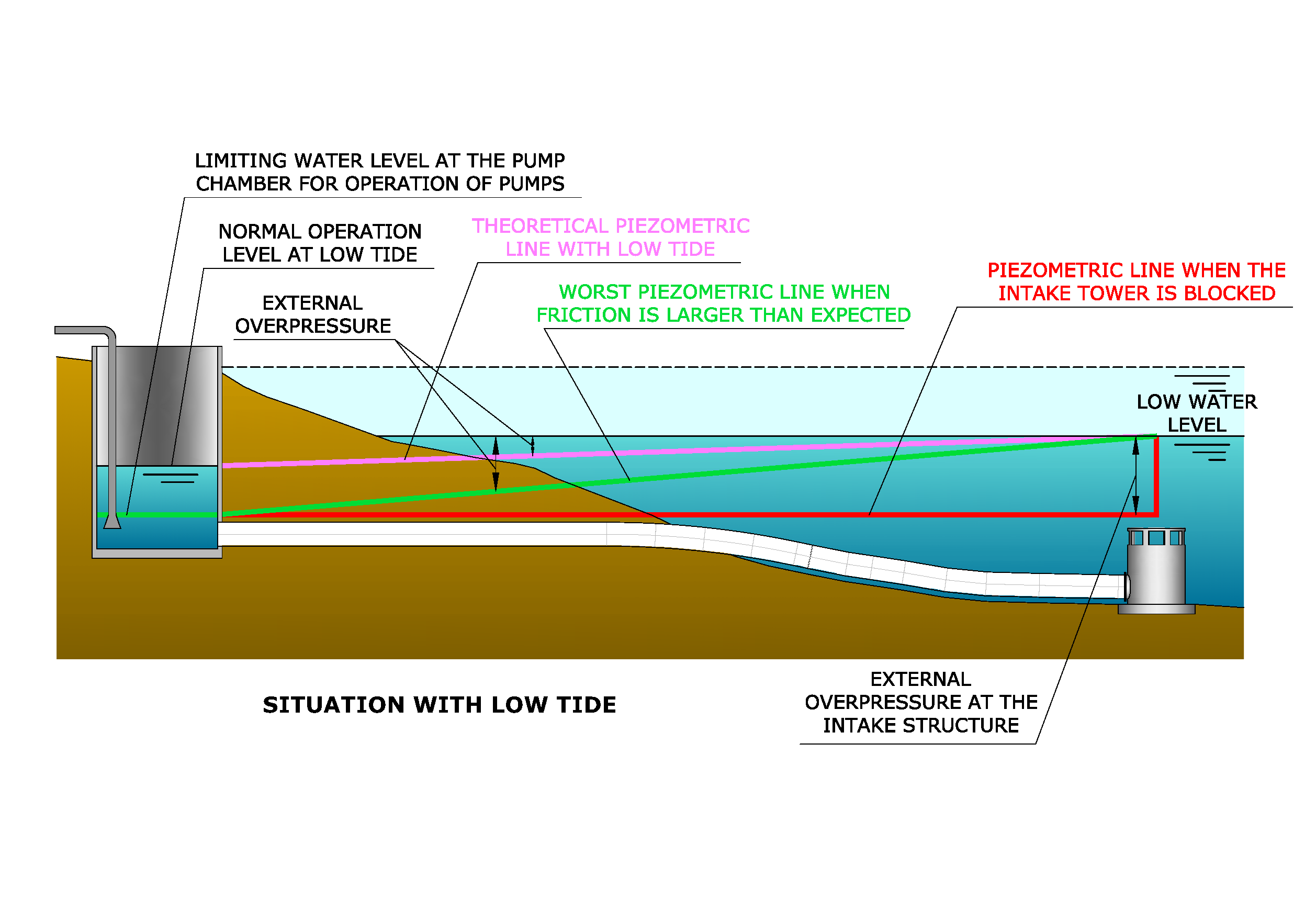
Figure 2: Different piezometric lines during operation of an intake (high sea level)
This situation can be worse, from a structural perspective, if it occurs during high tide, as shown in Figure 2. As the seawater level is high, there is more margin for the plant operator to continue pumping water in “no-expected conditions”, as shown with the green and red lines. The problem is that the external overpressure in the pipe and in the intake structure (black vertical arrows) can be even higher than what happens with low tide.
It is very important to inform operation controllers what the lowest water levels are that can be accepted in the pump chamber, according to the design assumptions for the intake pipe. Quite often, in operation, performance of the pumps is the only aspect that is checked but there are some situations in which the pumps can work properly whilst creating too low a level at the pump chamber, which could lead to structural problems in the intake pipe(s). A good way to be warned about possible misfunctioning of the system is to check the flow and compare it with water level in the pump chamber and the sea level.
Although not discussed in this paper, the use of hypochlorite and compressed air (carefully studied) may be a way to avoid (or reduce) blockage of the intake.
The increase of head loss due to an increase of friction at the pipe internal wall can be avoided with proper maintenance and regular cleaning of the pipes.
Pigging is a very efficient and quick way to clean the pipes. To permit pigging, the design should be carefully prepared, allowing the pushing of the pig, its passage (without sharp elbows or big “T” connections) and its recovery at the end of the line. Depending on project requirement, special designs may be required for recovery of the debris extracted from the pipe.
If any of these risks should be avoided, the designer should assume that the piezometric line is horizontal, reaching the lowest possible level at the pump chamber and, at the same time, that sea water level reaches its highest possible level. An appropriate Elasticity Modulus of the HDPE should be chosen for this structural analysis.
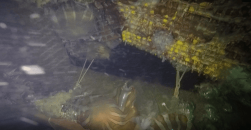
Figure 3: Intake structure broken grid due to jelly fish
Formulae for pipe buckling
It is important to understand the validity of the buckling verification formulae for buried pipes, shown in the AWWA M55. This section aims to draw attention to some uncertainties the authors find and gives their thoughts about them.
Increa’s analysis is focused on PE pipes as most of water intakes and outfalls for desalination plants are made of this plastic material. In this paper Increa present their understanding and doubts about the validity of the existing formulae, which also happens with other standards and rules.
With these formulae, the sum of the external loads must be equal to or less than the allowable buckling pressure (PcA), which is defined in the following way (only valid for solid wall pipes):
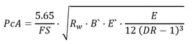
This expression is exactly the same as it is shown in other standards and manuals (and valid for any kind of pipe) as:
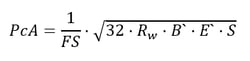
where:
- FS = safety factor, typically 2 for HDPE pipes.
- E’ = Sc * E’b composite modulus of soil reaction
- E’b= modulus of soil reaction of the pipe zone embedment
- Sc = soil support combining factor (from AWWA)
- DR corresponds to the ratio (external diameter of the pipe)/(thickness of its wall)
- S = EI / Dm3 Ring stiffness, which includes
E (the apparent modulus of elasticity of PE),
I (transversal inertia of the wall of the pipe) and
Dm (mean diameter of the pipe).
- Rw = 1 - 0,33 (Hw / H), water buoyancy factor.
- H is the depth of cover.
- Hw is the groundwater height above pipe.
If the pipe is installed submerged (under the sea, a lake, etc), it is not clear if Hw is the difference of hydraulic pressure between the external and internal water pressure or if it is the water table height (that is, for submerged installations, Hw=H). In the first understanding, Rw is a way to consider the reduction of resistance that happens when part of the external pressure is due to hydrostatic pressure. With the second understanding, this reduction is related to the loss of weight over the fill due to having part of the fill submerged. AWWA considers that Hw <H and it means that the lower value of Rw is 0.67. If we consider that Hw is the external overpressure, Hw could be larger than H and then, it is not clear if Rw can be lower than 0.67.
- B` soil elastic support factor, dimensionless:
![]()
The value of B’, corresponding to different heights of cover is the following:
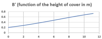
Figure 4: Function of the cover height in metres
It can be seen that the impact of this value of B’ on the PcA is rather small. For instance, if the cover changes from 1 m to 3 m, then the PcA increases by 17%.
A formula defined in the AWWA M-55 Manual is used to calculate the pressure qex acting on the pipe which should be smaller than the PcA. It calculates the overpressure on the pipe as follows:
qex = PE + PL + PES + Pv
- PE: weight of the ground above the pipe crown (earth pressure).
- Pv: vacuum pressure (with respect to the outside of the pipe), that is, the difference between external and internal water pressure.
- PL: live loads (must be considered with short time flexural modulus).
- PES: surcharge loads (commonly not existing in marine installations).
For covers under 15 m, the Marston theory is generally used to determine the loads imposed on buried pipe by the soil surrounding it (PE):
PE = γ.H,
Where γ is the specific weight of soil (water presence shall be considered, using submerged, apparent or dry density, depending on the level). For marine pipes, it is clear that the submerged density should be used.
The increase of cover has a double effect: it increases the weight of ground over the pipe but, at the same time, it increases the rigidity (horizontal reaction) at both sides of the pipes.
The problem comes in the situations where the external hydraulic overpressure (intakes) is high, for instance, larger than the cover height (Hw>H). In this case, the high level of qex is not accompanied by a growth of the rigidity of the fill at both sides of the pipe. This problem is analyzed in the investigations developed by Luscher (Luscher, 1966 and Luscher 1965).
It is also important to understand that the apparent modulus of elasticity (E) depends on the duration of the charge. This means that each charge should be compared with the allowable external pressure that corresponds to its E. Increa suggest gathering charges in three groups, depending on their duration: short, medium or long term.
Increa also points out that AWWA states that the previous formulae shall be used with engineering judgement if the cover is low, that is, where H<1.2 m and where H<D. In some literature, such as the Handbook of PE plastic pipe, by the Plastic Pipe Institute, PPI, it is more conservative and states this situation happens where H<1.5 D. In these cases, a way to avoid risks is to use the Timoshenko formulae (shown in the Manual as Eq 5-10), that does not consider the presence of any restriction (soil) around the pipe.
AWWA states that Timoshenko formula (that is, without considering the effect of the soil) should be used when a pipe is subject to internal vacuum. Increa understands that this statement refers only to vacuum due to water hammer. The examples shown in this manual do not add the rest of external charges for verifying the safety; it considers short term E of HDPE, as it only includes the short-term charge. Using Timoshenko formula for any Pv, in the case of buried pipes, would lead to overly conservative designs, especially when the geotechnical properties of the trench fill material are good.
Increa understands that there is another element to consider, and it is the relationship between the Pv and the qex. When Pv is more than 50% of qex, then special judgement should be developed.
Increa is currently working to bring more light into the analysis of buckling of buried pipes.
Figure 5 shows the structural consequences of buckling at an intake (helically welded PP) pipe, where filling height was very small:
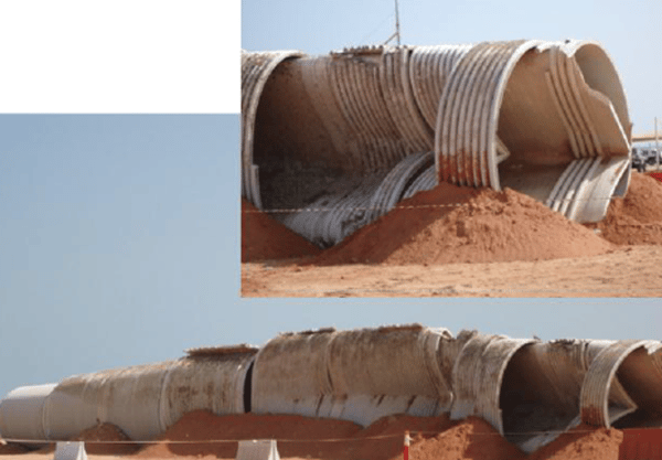
Figure 5: Collapse of an intake pipe due to buckling
Cover of the pipe
An important acting pressure over the pipe is PE and it is proportional to the height of cover over the pipe.
Changes of ground cover over the pipes, due to littoral dynamics, should be considered in buckling and opalisation verification of pipes, both for intakes and outfalls. It is very important to realise that, in the case of intakes, a decrease of cover can mean a reduction of safety, as described above.
The execution of works at the coast can completely change the marine hydrodynamics and can create new erosion and sedimentation zones. Figure 6 shows what happens at the coast when a marina is constructed close to a beach (the example is taken from Costa Rica, where Increa is currently designing some outfalls). The left hand image shows the coastline existing before the construction of a port and the picture at the right shows the same area, after its construction.
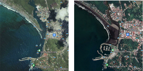
Figure 6: Evolution of the shoreline due to the construction of a marina
Geotechnical properties of filling of the trench
Structural problems also happen at the pipe when the quality of the trench fill material on both sides of the pipe does not meet the required stiffness. For installation under the water, Increa recommends using high quality material (granular fill without fines) instead of compacting the filling, as the process of compaction is very complex, and, additionally, the humidity is usually so high that the necessary levels of compaction are impossible to reach.
Many constructors wish to use the same material they dredged for filling the trench, in order to reduce cost. A complete campaign of easy trials (specifically, granulometry) should be done to validate this material. The presence of areas of silty material should be checked in order to avoid its use.
It is also important to avoid any possibility of fine sediment ingress into the trench before filling it. If it happens, it should be removed from the trench before the proper filling is executed.
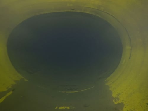
Figure 7: Internal view of brine outfall pipe with significant ovalisation due to poor trench filling
Air inside outfalls
The presence of air inside pipes can create many problems, as buoyancy of the pipes or reduction of their hydraulic capacity. In this chapter, we will focus on problems in outfalls rather than intakes. In regard to the presence of air in an outfall pipe, Increa has found two main problems in existing plants:- If the first stretch of the outfall pipe (part of the onshore section) is placed above the sea level, when there is no flow (or it is low), the initial part of the flow is not in “full section”. When starting (or increasing) the flow, if it is high and comes abruptly into the pipe, it can drag air into the section of the pipe that runs under the water and this air could lead to the buoyancy of the pipe (and, consequently, deformation and structural damage of the pipe).
In the previous situation (section placed above the sea level), it is important to have high slopes, so that the air will travel upwards when the section is filled. These slopes should be combined with air valves conveniently located. If this situation is not properly addressed, problems of buoyancy (due to tidal variation) or reduction of hydraulic capacity can occur. - It is very common to have a hydraulic jump at the outfall chamber. A study of transient situations (especially for sudden stop of flow that could lead to the entrance of air in the pipe) is always needed. Additionally, it is important to understand that this jump can create air bubbles that could travel with the brine flow along the pipeline and get blocked at some locations (e.g. manholes or changes of slope), leading to a reduction of hydraulic capacity of the pipe and, again, buoyancy problems.
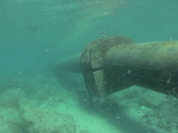
Figure 8: Outfall pipe rising towards the sea surface due to entrained air. At the left, the intake pipe can be seen. Both pipes were initially placed in the same trench, but buoyancy forces lifted the outfall.
The use of air valves and vents, conveniently placed, are the best way to solve these issues. As brine is very aggressive, the material of air valves should be carefully chosen. Placing air vents under the water is possible but they are difficult to maintain.
Sudden stop and start of intake pumps
There is always an interface between the design of marine pipes and the rest of the plant, and it should be carefully studied. In the case of the intake, the interface is commonly the seawater pump station, and it is important not to forget the analysis of transient situations.
The transient situation to be analysed is what happens when there is a sudden stop of all the pumps (for instance, due to an electrical failure). If the size of the intake pipes is large compared to the horizontal area of the pump and filter chambers, then the water level can rise and flood the pump rooms. The situation is easy to understand, as there is a large mass of water travelling through the pipes towards the pump station and this momentum is not easy to stop.
The transient situation that happens when there is a sudden start of pumps (which could lead to emptying the pump station and part of the pipes) can be avoided by starting pumps slowly, one by one.
The use of check valves (Duckbill, etc)
Check valves can be placed on the ports of the outfall diffuser. They were initially used in outfalls for sewage installations, in order to avoid saline intrusion and the entrance of life into the pipe, in case of stoppage of flow. In the case of brine outfalls, saline intrusion is not expected, and these valves would not ordinarily be necessary. Nevertheless, when there are significant changes of flow and different operational situations that can vary quickly, the use of duckbill valves can be used to increase the initial dilution in cases when there is a reduction of the brine flow. In this case, as the opening gets smaller, higher velocities (than the situation without the valve) occur.
Having duckbill valves placed at the ports has the disadvantage of creating structural problems in some outfalls when a tsunami arrives and a stop of brine flow occurs. When the trough passes over the pipe, it empties, but when the crest comes over the pipe, it cannot be filled, an external over-pressure acts on the pipe and buckling of the wall may happen.
It is also important to consider the tide levels when there is no brine flow. In this case, a similar situation can happen at the pipe. During low tide level, brine leaves the outfall and when tide rises, water cannot enter into the pipe and an external overpressure acts on the pipe.
Conclusion
The design of water intakes and outfalls for desalination plants is a complex task and should consider all of the operating situations that could happen in the future.
Operation of the plant (in this case particularly the pump station) is a critical consideration. The designer should be aware of the situations that operation can introduce and the consequences it can have on the installation. Similarly, plant operators must be aware of the impacts of their actions on the installed infrastructure.
The relationship between the design and operation is essential. If future operation and coast hydrodynamics cannot be controlled or limited, the designer should understand and consider any condition that could happen in the future as a result of these uncontrolled conditions.
Buckling of the pipe should be carefully addressed when high head losses in the intake system may be experienced.
The presence of air (a risk that can occur mainly inside poorly designed outfalls) can have catastrophic consequences, due to buoyancy. This risk must be carefully assessed and properly mitigated.
The Author
Eloy Pita is the founder and general manager of Spanish consulting firm Increa. He has more than 27 years of experience in marine works (ports, outfalls, caissons, quays, etc.), foundations and structures, beams, and precast concrete (particularly in maritime environments), anti-noise walls, pipelines, formwork, quality systems and environmental acoustics.
Share