


A proposed safe design of the reverse osmosis system

DOWNLOAD THE PAPER
Abstract
In a seawater reverse osmosis (SWRO) desalination plant, the SWRO system includes the high-pressure pump, the high-pressure piping, the energy recovery equipment, the pressure vessels and the RO membranes. The membranes are the most delicate part of the plant and are subject to continuous operational variations during water production.
Designers of plants propose various solutions to protect the RO system through the use of mechanical and control/automation devices.
This paper aims to present several design and operational considerations and address them through a proposed technical solution. With the correct combination of instruments, the RO membranes are protected and the overpressure in the system can only happen due to malfunction or failure of the instruments.
Further to these design considerations and additional manufacturing precautions which have to be in place during the implementation of a new desalination plant, there are occasions where the desalination plants make use of a pressure relief valve within the RO system in order to compensate for any potential overpressure in the system. This protection may not always be effective under all scenarios the RO system may encounter and therefore may not always protect the RO membranes.
Introduction
In a seawater reverse osmosis (SWRO) desalination plant, the system includes the pump, the high-pressure piping, the energy recovery equipment, the booster pump, the low-pressure piping, the pressure vessels and the RO membranes. The membranes are the most delicate part of the system and are subject to different requirements during the operational scenarios.
For this reason, each element (pipes, pressure vessels, etc.) of the system is designed for the worst condition (e.g.: highest pressure, lowest temperature, or any design combination which can be considered the most extreme design condition) and a number of instruments are installed within the RO system (refer to Figure 1) in order to protect the RO membranes from any potential harm.
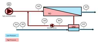
Figure 1: RO system sketch
General background
The safety of the RO system must be considered fundamental to the design and construction of a new SWRO Plant. The engineering of the RO system should be carried out by designing each component to the maximum potential pressure in the system based on the worst-case scenario that the system can physically realise.
Additionally, the operation of the system will add a number of scenarios that the RO system, as a whole, must be able to withstand. In fact, there are several potential failures in the system which might lead the system to exceed the design pressure mentioned above (overpressure). These scenarios should be duly verified during the design stage and the necessary protections must be implemented in the system design and control.
Research conducted
Design considerations
While designing the RO system, the designer needs to take into consideration many aspects – both technical and non-technical. These include the conditions dictated by the site environment where the system needs to be working in (e.g. seawater quality, temperature, humidity) or employer/contractual requirements which, by definition, impose on the design of the RO system.
Based on the above, the designer starts the exercise with the RO membrane design which is considered the most crucial element. The design is done by running a significant number of membrane projections depending on the seawater quality.
The envelope of results provided by the membrane projections can identify the worst-case scenario which the rest of the system should be designed for.
Operation considerations
The RO membranes have specific requirements that should be controlled during operation (e.g. pressure / velocity increase during start-up, differential pressure during operation or permeate back-pressure when the system is stopped), together with the specific operating conditions that are directly connected to the seawater quality conditions (especially TDS and temperature).
A typical example for pressure requirements based on seawater conditions is depicted below in Table 1: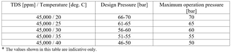
Table 1: Membrane pressure requirements*
The high-pressure pump (HPP) is controlled to ensure that the system is operated under the design pressure conditions defined by the seawater quality.
Additionally, the system should be protected according to the maximum operation pressure for each scenario. Therefore, various analogic instruments are included in the system, such as pressure and flow transmitters, that allow for operation and monitoring of the system for each case.
Some examples of control of the HPP are depicted below:
a) Control by pressure with the transmitter located on the membrane feed:
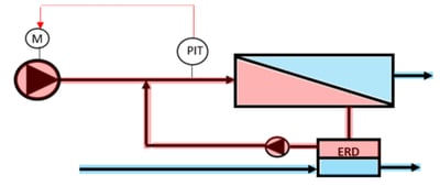
Figure 2: High pressure pump operation 1
b) Control by flow with the flowmeter located in the HPP line:
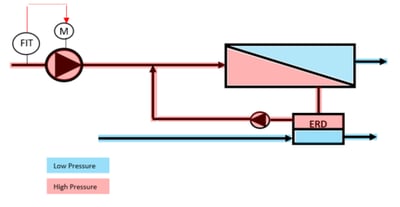
Figure 3: High pressure pump operation 2
c) Control by flow with the flowmeter located in the permeate line:
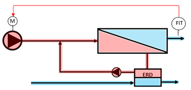
Figure 4: High pressure pump operation 3
The following figure shows some of the instruments that can be installed in the system for control and monitoring:
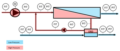
Figure 5: Instruments in the system
The combination of instruments selected for each system depends on the HPP control selected, the design range requirements, the energy recovery system installed, etc., and the designer is responsible
to select the best combination.
In addition, the system should adopt protection values based on the operation and the seawater conditions. For example, the RO membrane pressure limit is not the same during winter (cold water) and summer.
Overpressure protections
In addition to logic and operation protection, some plants include an extra safety device for overpressure that does not depend on data processing. This can be mechanical (e.g. pressure relief valve) or electrical (e.g. pressure switch wired to the pump).
The pressure relieve valves (PRV) are installed as a “weak point” in the system; if the system reaches the PRV manufacturing setting pressure, the device will release the excess pressure by discharging water out of the RO system, usually to the atmosphere. These elements will not stop the system, nor protect the RO membranes since they are not directly connected to any functioning RO system equipment item. Moreover, they could be considered a safety risk due to the amount of water flooding into the RO building. Even if necessary provisions are made to discharge in a dedicated controlled location outdoors, an environmental concern remains due to the wasted water and energy which occurs.
Alternative solutions are available thanks to technical and technological devices available in the industry, ensuring a correct combination of logic sequence, selection of control and monitoring equipment, and installation of dedicated devices keeping in consideration all the potential operational scenarios. Further considerations are documented in Section III.
Manufacturing considerations
The safety of the plant and particularly the RO system is not only addressed by a prudent and well-considered design but also by a number of manufacturing precautions and good practices. The standards address many testing and installation recommendations which should be taken into consideration during the manufacturing, construction, installation, and commissioning phases of the plant. All parties involved, from manufacturer and constructing entity to employer and third-party engineering company, should work closely together throughout the project lifecycle in order to deliver a safe plant.
Results
All of the considerations highlighted in the section above should be taken into account by the designer of the RO plant during the project’s early stages of engineering for the systems involved. Different approaches can be evaluated depending on the operational and design philosophy; however, safety must not be compromised.
Control and monitoring aspect
The design should consider separated elements for control and monitoring in order to protect the system. Some examples of logic protections are depicted below:
a) Flow rate at the HPP should be the same as the permeate flow rate:
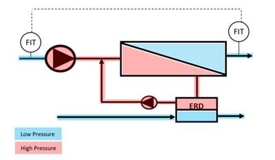
Figure 6: Scenario A
During operation, the HPP flow should be the same as the flow on the permeate side. In the event that the system detects a deviation, an interlock should be applied and the system should stop. The reason for this trip could be: if there is a malfunction of the permeate flowmeter providing a lower value than reality and the control of the HPP is performed with this FIT, the HPP will automatically increase the speed in order to reach the set point value. This will create a difference in both FITs and the system should stop. The same will apply if the malfunction of the FIT provides a higher value: the HPP will reduce the speed.
This situation (different flow in rate in HPP and permeate) without the logic protection (Scenario A) will not overpressure the system to a level that a non-process element1 could act as a protection but can cause damage of the membrane if the system continues in operation. In case the logic is implemented, the system will stop avoiding membranes’ damage.
b) Membrane brine outlet pressure should not be less than 2 bar of the membrane inlet pressure:
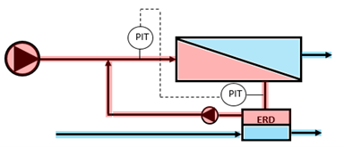
Figure 7: Scenario B
During operation, the membrane inlet pressure should be higher than the brine pressure, but not more than 4 bar (as mechanical limit). Nor should it be higher than a percentage in reference to previous data (trend). In case the system detects a deviation, an interlock should be applied and the system should stop. The reason of this trip could be: if there is a malfunction of the pressure transmitter in the membrane inlet providing a lower value than reality and the control of the HPP is performed with this PIT, the HPP will automatically increase the speed in order to reach the set point value. This will create a difference in both PITs and the system should stop. The same will apply if the malfunction of the PIT provide a higher value: the HPP will reduce the speed.
This situation (without the logic protection) can over pressurise the system if action is not taken in time and, depending on the seawater conditions at the moment of this event, the non-process element1 would act as mechanical protection for the system but will not protect the membranes. Implementing the logic will not only protect the system but also the membranes.
These are only two examples of logic protection. The RO system can be designed to incorporate many others. More importantly, all logic protections can be implemented at the same time providing redundant protection based on operation performance and system reaction to operation logic in place.
[1 Non-process elements refer to those protections that act (mechanically or electrically) based on basic criteria (yes / no) without the use of a logic (or e.g. pressure switch or pressure relieve valve).]
Switch devices
High pressure switches (PSH) can be directly wired to the HPP. Therefore, if the RO system reaches the maximum mechanical design pressure, the PSH will act and stop the HPP, reducing immediately the pressure in the system and reducing the time that the system is exposed to the maximum mechanical design pressure.
This protection will act in case of human error (operator modifying the logic or bypassing signals) since the logic protection will stop the system prior to reaching the manufacturing set point of the switch.
Using a switch device that stops the system is the most suitable solution from a safety point of view. Other devices (such as PRV) will release the pressure of the system but will discharge the water to the atmosphere (possibly causing damage to external elements). They will not stop the system which will continue in operation at the limit of maximum mechanical pressure.
Design
The designer should consider elements that will allow not only for protection of the system with logic protection but also for learning membrane performance over the years thereby helping to improve the operation and optimise the operation costs of the plant. In addition, for further protection, more solutions can be considered (e.g. high pressure switch) instead of PRV in order to eliminate the potential safety or environmental risks caused by PRVs.
Conclusion
With the correct combination of instruments, RO membranes are protected and the risk of over pressurisation in the system is limited to malfunction or failure of the instruments. Even though failure of a flowmeter or pressure transmitter is very unlikely, the designer has the responsibility to ensure that these scenarios are covered. In the majority of cases, logic protection is the most suitable option and the system is programmed accordingly. Additionally, the standards address a number of recommendations for safe installation on site and further factory or site testing to guarantee future correct functioning of each element installed.
Further to these design considerations and additional manufacturing precautions which have to be in place during the implementation of a new desalination plant, there are still occasions where desalination plants make use of a pressure relief valve located in the RO system in order to compensate for any potential overpressure in the system. Even if the system is properly designed and the manufacturing recommendation followed, this protection may be ineffective for some scenarios which the RO system can encounter and (in particular) may not protect the RO membranes. They could even be considered a safety risk due to the amount of water flooding into the RO building unless necessary provisions are made to discharge in a dedicated controlled location outdoors. Nevertheless, it still remains an environmental concern due to the wasted water and energy.
In conclusion, the design of ROs system must aim at all costs to be safe and reliable under all operating conditions. A number of technical solutions can be adopted including the installation of more suitable non-process protections for overpressure, such as a high-pressure switches in the RO rack. Although these will not protect the RO membranes, they will not add additional risks to the RO plant. The need for pressure relief valves can be overcome by the solutions offered above thereby avoiding the environmental and safety risks mentioned above.
The Authors
Maria Eugenia Beltran Lezaun is currently the Desalination Department Manager for ILF Abu Dhabi. Maria Eugenia is a desalination design and commissioning expert with more than 15 years of experience on SWRO plants including Barka I (Oman), Nungua (Ghana), Tuas (Singapore) and Taweelah (UAE) throughout the project lifecycle.
Roberto Mangano is the Managing Director for ILF Abu Dhabi. He has a successful track record of working in the Middle East, Central America and Europe on projects as a Project Director/Project Manager for strategic desalination projects. Roberto holds a Masters Degree in Industrial Chemistry and specialises in membrane desalination.
Simone Puzzo is the Head of Water & Environmental Projects for ILF Abu Dhabi. His latest contribution includes successful completion of projects such as Taweelah IWP, UAE (Deputy Project Manager), Umm Al Quwain IWP, UAE (Deputy Project Manager), Shuqaiq 3 IWP, KSA (Deputy Project Manager) and Yanbu 4, KSA (Technical Manager).
Share